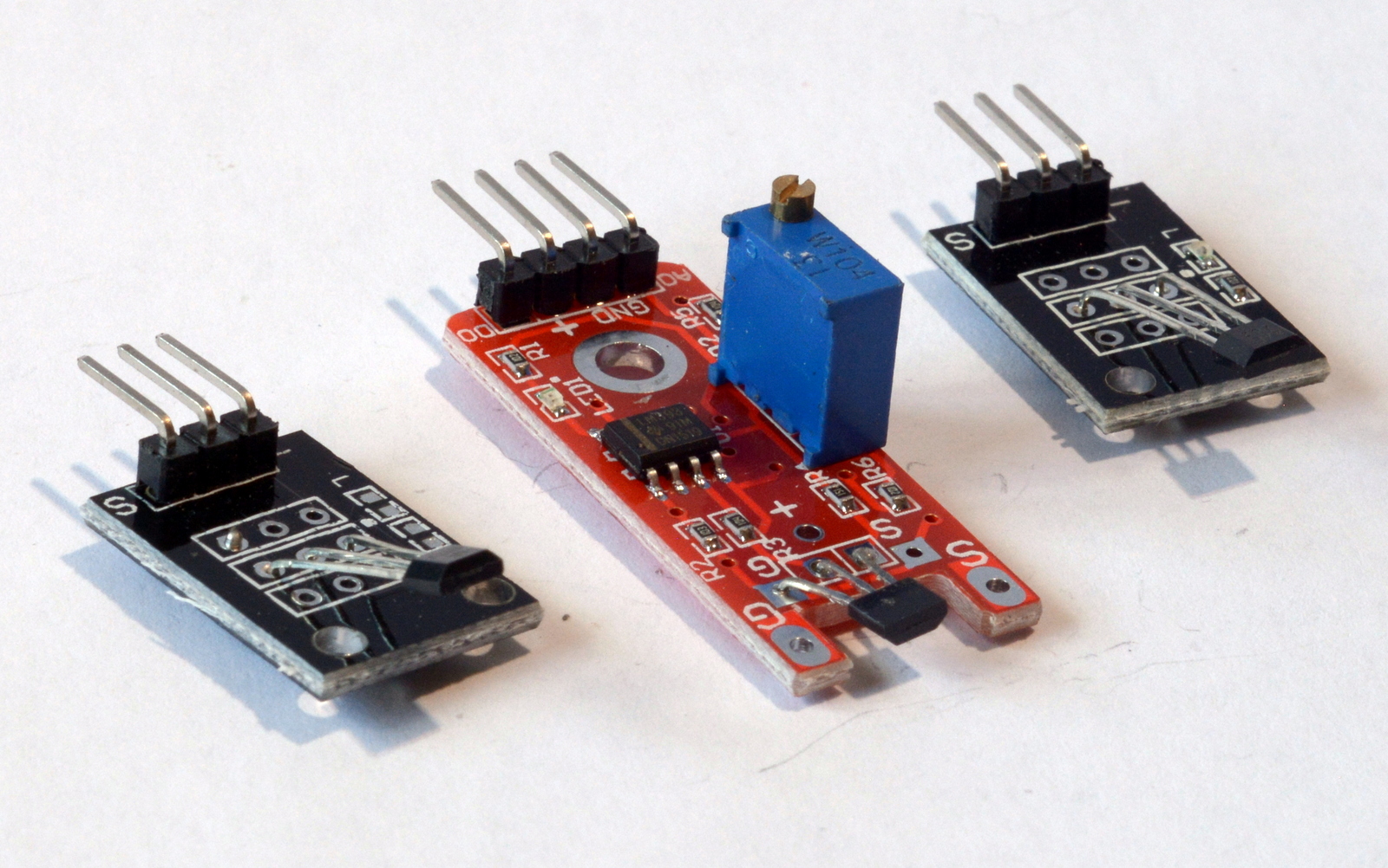
Tech details:
- Operation voltage 3.3 V, 5 V
- Temperature range of -40 °C to 85 °C
- Current input/output max 8/20mA
- Response time: 3uS (very fast)
Connectivity:
4 pin connector, pins as follows:
- AO: Analog Output
- G: 0V Ground
- +: 3.3V – 5V Supply
- DO: Digital Output
3 pin connector, pins as follows:
- GND (-): Ground
- VCC (+): 3.3V – 5V Supply
- S: Signal
Both versions of the sensor can be connected directly to GPIO pins.
What does it do?
Hall sensor module is a very responsive switch that is activated by a magnetic field. It can be triggered by a natural magnet or an electromagnet. High response rates allow readouts to be taken even at frequencies of 100kHz. Most popular uses are in proximity sensing detecting speeds of spinning objects or as door sensors. Due to nature of the sensing (contactless) hall sensor module is very durable, and there is no wear associated with the use. Sensors come usually as non-latching however the latching versions are possible (sensor keeps the state after magnet has been removed until opposite polarity is introduced).
How to use it?
KY-003
This is an analog sensor module. The sensor goes HIGH on the S pin when a magnetic field is detected. The PCB contains a LED light that indicates when the sensor detects a field and a resistor to lower the current supplied to the board. It is possible to detect voltage changes, that occur when the magnetic field is applied. The value of the voltage on S pin would depend on a strength of a magnet and the distance from the sensor.
KY-024
This is an analog/digital module with a built-in potentiometer to adjust the sensitivity of the sensor. Analog output (AO) works in the same way as on the KY – 003. Digital output (DO) allows for a pure HIGH/LOW detection and adjusting the sensitivity of that detection with a potentiometer.
In both cases the GND(-) connects to any ground pin (black) on a Raspberry Pi, VCC(+) power supply (red) connects to the 3.3V on RPI and the signal (S or AO/DO) is linked to any GPIO pin (blue).
When using Hall sensor modules have to be mounted in a correct orientation. One side will respond to the N pole of the sensor while the other side will respond to the S pole.
Sample code:
You can test the Hall sensor using a python2 code from here.
import RPi.GPIO as GPIO

GPIO.setmode(GPIO.BCM)
GPIO_PIR = 24
print "KY-003 Module Test (CTRL-C = exit)"

GPIO.setup(GPIO_PIR, GPIO.IN, pull_up_down = GPIO.PUD_UP)
def printFunction(channel):
    print("Detected")
    GPIO.add_event_detect(GPIO_PIR, GPIO.RISING, callback=printFunction)
try:
    while True :
        Current_State = GPIO.input(GPIO_PIR)
        except KeyboardInterrupt:
GPIO.cleanup()
# Import required libraries
import RPi.GPIO as GPIO
import time
import datetime

# Tell GPIO library to use GPIO references
GPIO.setmode(GPIO.BCM)

print "Setup GPIO pin as input"

# Set Switch GPIO as input
GPIO.setup(17 , GPIO.IN)

def sensorCallback1(channel):
# Called if sensor output goes LOW
    timestamp = time.time()
    stamp = datetime.datetime.fromtimestamp(timestamp).strftime('%H:%M:%S')
    print "Sensor LOW " + stamp

def sensorCallback2(channel):
# Called if sensor output goes HIGH
    timestamp = time.time()
    stamp = datetime.datetime.fromtimestamp(timestamp).strftime('%H:%M:%S')
    print "Sensor HIGH " + stamp

def main():
# Wrap main content in a try block so we can
# catch the user pressing CTRL-C and run the
# GPIO cleanup function. This will also prevent
# the user seeing lots of unnecessary error
# messages.

    GPIO.add_event_detect(17, GPIO.FALLING, callback=sensorCallback1)
    GPIO.add_event_detect(17, GPIO.RISING, callback=sensorCallback2)

try:
# Loop until users quits with CTRL-C
while True :
    time.sleep(0.1)

    except KeyboardInterrupt:
# Reset GPIO settings
GPIO.cleanup()


