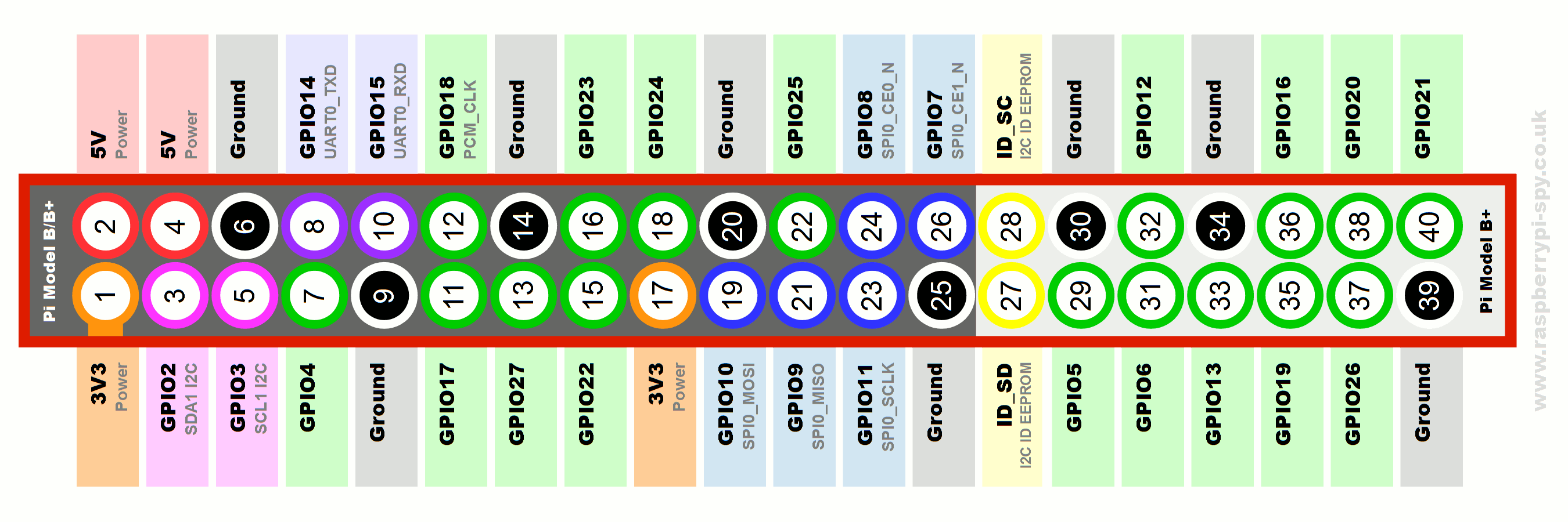
GPIO – general purpose input/output
Yes! These guys! Sticking out there like sore 40 thumbs. I’m sure, you have the general idea what these are for! This is where you attach those fancy cables to, before realizing that nothing works. The pins are split into 4 main types
- GPIO
- 3.3V
- 5V
- Ground
I hope you read this before you messed about with the pins and cables as there is a chance of killing the individual pins, sensors or your precious RPI alone!
Voltage pins are self-explanatory – RPI can supply power to your sensors or boards, either at 3.3V level or 5V. 3.3V is limited to 50mA (split pins 1 and 17) while 5V draws it directly from the micro USB and can have whatever is left after RPI has been powered up. Ground – is used to close the circuit, and any of the pins can be used interchangeably. Be careful not to short the 3.3V and 5.V pins as this can lead to the board damage.
Each GPIO pin is able to carry up to 17mA with the limitation of 51mA being available across all pins. For more power, hungry projects consider a separate power source.
GPIO is where the magic happens, as behavior of these pins depends on the software that uses it. The header provides 17 Pins that can be configured as inputs and outputs. By default, they are all configured as inputs except GPIO 14 & 15. They are also grouped in interfaces that are additionally available to you – expanding the connectivity of your RPI.
Plugging cables randomly won’t get you anywhere, and can cause serious damage to your circuits or RPI. Despite 5V pins provided, RPI operates on up to 3.3V current. If you connect higher voltage to any GPIO you will end up damaging it.
import RPi.GPIO as GPIO

# to use GPIO number not the pin physical number
 GPIO.setmode(GPIO.BCM)

#or to use the physical pin numbers (1-40) instead of GPIO number
 #GPIO.setmode(GPIO.BOARD)

# setting up pins as I/O
 GPIO.setup(3, GPIO.IN) #sets GPIO3 as INPUT
 GPIO.setup(4, GPIO.OUT) #sets GPIO4 as OUTPUT

# to assign pin input value to a variable
 input_value = GPIO.input(3)

# output to GPIO4
 GPIO.output(4, True)
To use any pin in a script you have to describe the pin in question ie. GPIO3 (for pin no 5) and declare how the pin is used. You can assign the pin as an Input or Output, or declare a specific interface. RPI will measure voltage levels on the pins and translate this into following states HIGH (3.3V present) and LOW (0V present) with about 10% tolerances.
When dealing with sensors or boards that output higher than 3.3V current – it has to be stepped down to prevent damage. You can do so by ie using Logic Level Converter.
Interfaces:

In addition to the general use of pins on the RPI, we have several interfaces available on the board expanding the connectivity of our microcomputer. Trading off few pins at the same time we can provide additional functions and cross connectivity with other micro boards. To have a closer look at what interfaces are available on your board – have a look on this interactive guide.
DPI (Display Parallel Interface)
This interface allows you to add VGA connection directly from the pins itself. Supported resolution ranges from 640 x 480 up to 1920 x 1024 @ 60fps. If you don’t want to use HDMI connection – simply wire these pins accordingly and the video output will be sent to your display. You would be able to drive another desktop through the pins, but bear in mind you will use 22 pins to do so!
GPCLK (General Purpose Clock)
This interface allows you to output a specific hardware driven frequency. You will sacrifice 3 pins to use it. Available frequencies are predefined.
JTAG (Joint Test Action Group)
The interface uses 11 pins and allows to test and debug circuits on your RPI. Chances are you will never need this. But since you have asked…
PCM (Pulse-Code Modulation)
If you are looking for another way of outputting high-quality audio – you can use 4 pins digital output that can be translated to DAC standard.
I²C (Integrated Circuit)
4 of the pins are available as I2C connections, allowing to communicate with a range of other devices supporting this standard. This way you can save other GPIOs on your RPI, for other purposes and communicate with various microcontrollers via this bus. You would be able to connect expansion boards to overcome RPI limitations. Using these allow also to reduce the GPIO hungry expansions like LCD displays, GSM/GPS etc. So if you ever find yourself lacking inputs/outputs on your RPI – look into expanding this bus.
SPI (Serial Peripheral Interface)
This is another standard that expands the connections of your RPI, using 11 pins allows chaining your compatible devices together and read out the output on separate pins. This interface allows linking several slave devices to a single master.
UART (Universal Asynchronous Receiver Transmitter)
One of the older interfaces that allow for interactions with a lot of controllers. The receiving end is required to have UART hardware onboard and commands are issued as 8-bit transfers with 1st and the last bits marking the start and the end of the message. Voltage levels are ignored, so message can be coded using 3.3V, 5v or at the even bigger current level.


