HomeRaspberry Pi1602 LCD Display with Arduino and Raspberry Pi

1602 LCD Display with Arduino and Raspberry Pi

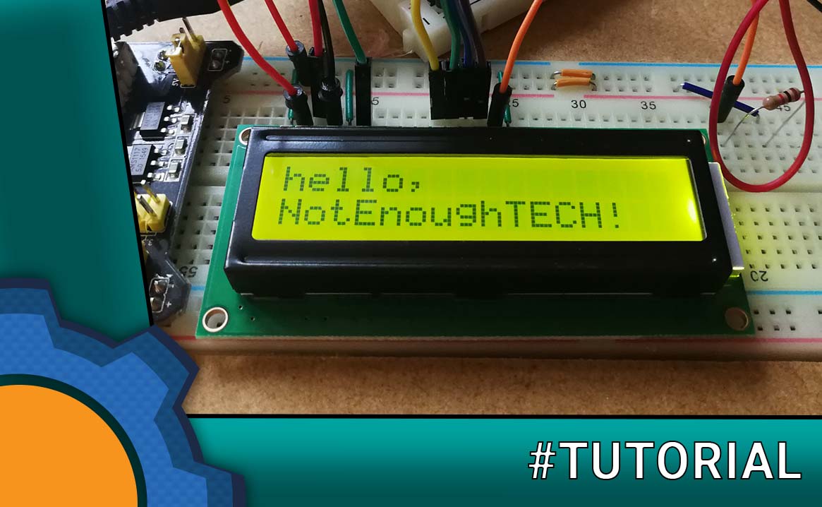
Displaying things on an LCD screen is as easy as going through a cup of jellybeans while writing this tutorial!

One of the ideas in my head involves a cup of jellybeans and an LCD display. Since I know how to operate the cup of jellybeans correctly, it was time to check if driving the LCD with Arduino and Raspberry Pi is equally easy. The short answer is: Yes!, if you read this post.

LCD with Arduino and Raspberry Pi

I have two 1602 LCDs which I will use to test with Arduino and Raspberry Pi. While most of the steps are straightforward, there is some voltage tweaking to get the display working correctly. If your display is correctly connected already, jump to the troubleshooting paragraph.

Connecting LCD

The 1602s have 16 pins. Not all will be used, but to drive the screen we going to need a fair bit of wires. Six of them are hooked up to the board, the rest one way or another will make their way to 5V and GND.

The 16 pins can be divided into groups:

  • data pins (11, 12, 13, 14) – we are using 4bit data
  • power pins (1, 2) – 5V operation
  • rs  – register select (4)
  • rw – read/write (5) – GND as we are writing values only
  • en – enable
  • LED backlight (15, 16)
  • LCD pixel brightness (3)

Most of the online tutorials will suggest a schematic that looks like this. It’s a bit confusing at first but there are things we can do to make it easy. The pins can be easily modified in the script.

const int rs = 12, en = 11, d4 = 5, d5 = 4, d6 = 3, d7 = 2;
LiquidCrystal lcd(rs, en, d4, d5, d6, d7);

The 16 pins LCD labels are:As long as you are consistent, you should not have any issues.

Everything is hooked up but LCD isn’t working?

I used two potentiometers in my schematics on purpose. Most of the guides give you some arbitrary resistor value that may, or may not work for you. This is where you can save yourself a headache and experiment a little. 

I’m using two 10kΩ pots to estimate a value of the resistor:

  • Pin3 – responsible for visibility of the LCD pixels (connected to GND)
  • Pin15 – responsible for brightness of the LED highlight (connected to GND)

Try turning the pots left and right until you are happy with how the LCD displays the content. As the resistance of the pots varies from 0-10K – it’s pretty easy to estimate the position of the pot (ie 60% to the right would mean 6k resistance) and therefore adding a correct resistor for your screen.

If you don’t have potentiometers at hand, grab a range of resistors from 1k-10k and see what works best.

Arduino Test

If you set everything up correctly, you shouldn’t have any issues with a test “hello world” example. The example is included in the Arduino IDE – liquid crystal library. Visit the library manager and search for just that.

ARDUINO IDE: LCD test
/*
  LiquidCrystal Library - Hello World
 
 Demonstrates the use a 16x2 LCD display.  The LiquidCrystal
 library works with all LCD displays that are compatible with the 
 Hitachi HD44780 driver. There are many of them out there, and you
 can usually tell them by the 16-pin interface.
 
 This sketch prints "Hello World!" to the LCD
 and shows the time.
 
  The circuit:
 * LCD RS pin to digital pin 12
 * LCD Enable pin to digital pin 11
 * LCD D4 pin to digital pin 5
 * LCD D5 pin to digital pin 4
 * LCD D6 pin to digital pin 3
 * LCD D7 pin to digital pin 2
 * 10K resistor:
 * ends to +5V and ground
 * wiper to LCD VO pin (pin 3)
 
 Library originally added 18 Apr 2008
 by David A. Mellis
 library modified 5 Jul 2009
 by Limor Fried (https://www.ladyada.net)
 example added 9 Jul 2009
 by Tom Igoe
 modified 25 July 2009
 by David A. Mellis
 
 
 https://www.arduino.cc/en/Tutorial/LiquidCrystal
 */

// include the library code:
#include "Wire.h"
#include "Adafruit_LiquidCrystal.h"

// initialize the library with the numbers of the interface pins
Adafruit_LiquidCrystal lcd(12, 11, 5, 4, 3, 2);

void setup() {
  // set up the LCD's number of rows and columns: 
  lcd.begin(16, 2);
  // Print a message to the LCD.
  lcd.print("hello, world!");
}

void loop() {
  // set the cursor to column 0, line 1
  // (note: line 1 is the second row, since counting begins with 0):
  lcd.setCursor(0, 1);
  // print the number of seconds since reset:
  lcd.print(millis()/1000);
}

You should see a “hello world” with a small timer counting up in the second line.

Raspberry Pi test

Installing the libraries is not as neat as with Arduino IDE. However, it takes only a few steps to get the test code running. Download the git repository:

git clone https://github.com/adafruit/Adafruit_Python_CharLCD.git

Install the LCD library:

sudo pip install adafruit-charlcd

Navigate inside the folder Adafruit_Python_CharLCD and run the installer:

sudo python es_setup.py

Then you can have fun with samples located in the examples folder!

RASPBERRY PI PYTHON: LCD test
#!/usr/bin/python
# Example using a character LCD connected to a Raspberry Pi or BeagleBone Black.
import time

import Adafruit_CharLCD as LCD


# Raspberry Pi pin configuration:
lcd_rs        = 27  # Note this might need to be changed to 21 for older revision Pi's.
lcd_en        = 22
lcd_d4        = 25
lcd_d5        = 24
lcd_d6        = 23
lcd_d7        = 18
lcd_backlight = 4

# BeagleBone Black configuration:
# lcd_rs        = 'P8_8'
# lcd_en        = 'P8_10'
# lcd_d4        = 'P8_18'
# lcd_d5        = 'P8_16'
# lcd_d6        = 'P8_14'
# lcd_d7        = 'P8_12'
# lcd_backlight = 'P8_7'

# Define LCD column and row size for 16x2 LCD.
lcd_columns = 16
lcd_rows    = 2

# Alternatively specify a 20x4 LCD.
# lcd_columns = 20
# lcd_rows    = 4

# Initialize the LCD using the pins above.
lcd = LCD.Adafruit_CharLCD(lcd_rs, lcd_en, lcd_d4, lcd_d5, lcd_d6, lcd_d7,
                           lcd_columns, lcd_rows, lcd_backlight)

# Print a two line message
lcd.message('Hello\nworld!')

# Wait 5 seconds
time.sleep(5.0)

# Demo showing the cursor.
lcd.clear()
lcd.show_cursor(True)
lcd.message('Show cursor')

time.sleep(5.0)

# Demo showing the blinking cursor.
lcd.clear()
lcd.blink(True)
lcd.message('Blink cursor')

time.sleep(5.0)

# Stop blinking and showing cursor.
lcd.show_cursor(False)
lcd.blink(False)

# Demo scrolling message right/left.
lcd.clear()
message = 'Scroll'
lcd.message(message)
for i in range(lcd_columns-len(message)):
    time.sleep(0.5)
    lcd.move_right()
for i in range(lcd_columns-len(message)):
    time.sleep(0.5)
    lcd.move_left()

# Demo turning backlight off and on.
lcd.clear()
lcd.message('Flash backlight\nin 5 seconds...')
time.sleep(5.0)
# Turn backlight off.
lcd.set_backlight(0)
time.sleep(2.0)
# Change message.
lcd.clear()
lcd.message('Goodbye!')
# Turn backlight on.
lcd.set_backlight(1)

Conclusion

As you can see, driving an LCD with Arduino and Raspberry Pi are not as scary as you may think. Did I mention, that these libraries support NodeRED? No? Go and take a look! I’m going to use one in one of my next projects. You can download the files from the link below.

Project Download

Download project files here. Bear in mind that Patreon supporters have early access to project files and videos.

PayPal

Nothing says "Thank you" better than keeping my coffee jar topped up!

Patreon

Support me on Patreon and get an early access to tutorial files and videos.

image/svg+xml

Bitcoin (BTC)

Use this QR to keep me caffeinated with BTC: 1FwFqqh71mUTENcRe9q4s9AWFgoc8BA9ZU

M5Paper

Programable, ESP32 based awesome dev platform with 4.7 e-ink display by M5Stack

More HATs

client-image
client-image

Argon One M.2

Enclose Raspberry Pi 4 inside this great case with custom I/O, cooling and GPIO and M.2 SSD support

More cases on

client-image
client-image

Best Raspberry Pi Projects

How to use Raspberry PI as WOL (wake on lan) server

0
While you could wake up your PC from a mobile directly, having a dedicated server capable of doing so is the best solution. The reason is simple. You can hook up as many devices as you wish with a single endpoint. This is why Raspberry Pi is perfect for this.

Slow Internet Warning

0
From time to time my Internet grinds to a stop. Since Raspberry Pi 4 comes with a 1Gbps Ethernet, I decided to take advantage of it and create a reporting system in NodeRED that will monitor and report when the ISP is not keeping the contractual agreements. Works with Alexa, Google Home, Android and Windows 10.

How fast Raspberry Pi NAS is?

0
Let's see how fast Raspberry Pi NAS really is?

Argon18: Argon ONE SSD modification

0
Argon One case just got better - now you can boot it from USB without ruining the design thanks to Argon 18: Argon One SSD modification

HOW TO...

How to boot Raspberry Pi 5 from NVMe M.2 SSD

0
This is how you can boot your Raspberry PI 5 from NVMe in 10 min! Check out these easy instructions

It took me 2 months to boot CM4 from NVMe

0
Complete beginners guide to Compute Module 4 boot from NVMe.

Raspberry Pi Zero 2 W vs other Zero boards

0
It's time to test the Raspberry Pi Zero 2 W against other Raspberry Pi boards from Zero series: power, WiFi, temperature and core performance

C/C++ and MicroPython SDK for Raspberry Pi Pico on Windows

0
A guide to SDK toolchain for Raspberry Pi Pico and C/C++ , Micropython on Windows.

A comprehensive guide to Grafana & InfluxDB

0
How to use Grafana and InfluxDB on Raspberry Pi for IoT sensors in home automation