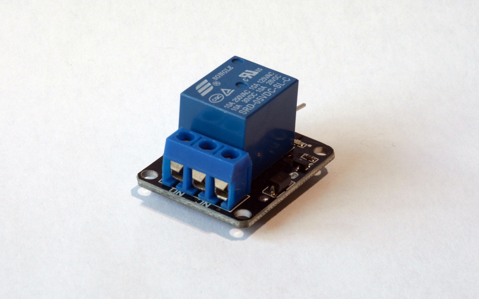
Tech details:
- Control signal: 5V-12V
- Current requirements: ~85 mA
- Max current: 10A/250V AC or 10A/28V DC
- Response time: 10msec
- Operating Temp: -25/+70 C
Connectivity:
3 pin connector, pins as follows:
- GND: 0V Ground
- VCC: 5V-12V
- Signal: 5V (see below)
Relay Module KY-19 requires 5V signal to control it. This means that additional circuit is needed to control it through the Raspberry pi GPIO. It is possible to use a transistor to do this. It is possible to control the relay from 3.3V pin, however, depending on the relay module the switch signal may not register. This is mostly an issue due to the current draw. GPIO pins might not be able to provide enough current to the relay. This is especially the case when multiple relays are used.
What does it do?
Relay Module KY-19 is a digital relay module which allows high voltage/current to be switched on or off using circuit-level power. If you wish to control an electric circuit a relay can be used to imitate the mechanism of a manual switch. When a voltage is applied to the module, it allows the flow of the current. This way you can turn on and off various high power devices like lights, motors, appliances.
How to use it?

The Relay Module KY-19 has 3 terminals. This is where your high voltage circuit is plugged to. The relay should be connected to the power source (+) and the device it will operate. Terminals mentioned are labelled as follows NO (normally open) COMM (common) and NC (normally closed).
When a relay is not powered, NC and COMM are connected and current can flow through. When the relay is powered the connection is made between NO and COMM. You can use the signal pin to reverse the switch at any time by supplying the HIGH/LOW signal to the board.
Depending on your project, you should consider the Relay Module KY-19 terminals and wiring. This way you can decide if your device will stay powered if the power is cut off from the controlling unit.
Sample code:
You can test the relay using a python2 code from here.
import RPi.GPIO as GPIO
import time

GPIO.setmode(GPIO.BCM)
GPIO.setup(2, GPIO.OUT)
GPIO.output(2, GPIO.HIGH)

# main loop
try:
  GPIO.output(2, GPIO.LOW)
  time.sleep(2);
  GPIO.output(2, GPIO.HIGH)
  time.sleep(2);
  print "Works"
  GPIO.cleanup()
  print "Good bye!"


